Here are some more detailed photos. Some parts are more complicated than they should be because of a mistake I had to correct for: I perfectly centered the rectangle in the plywood circle assuming that the centers of the CRT and monitor chassis lined up. They didn't, which caused the monitor to be off-center in portrait mode. I had to make some last minute quality adjustments to fix that by basically moving the rectangular cutout (enlarged it on one side and filled it in on the other). This worked, but introduced a new problem: it unbalanced the monitor so when you put it in portrait mode, it would swing back to rest at a crooked position. Attaching a counterweight to one side to balance it fixed it.
Here is a front view of the rotating monitor frame mounted inside the cabinet. The frame is tilted backwards to match the angle of the cabinet. The rough cuts on the inside of the frame are the result of more last minute quality adjustments with a jig saw, chisel and exacto knife.
The 2x4 frame is held to the sides of the cabinets with lots of wood glue and drywall screws. The frame also sits on nailing strips on the bottom and back. Here is a view from the back of the cabinet with the bicycle rim and plywood installed:
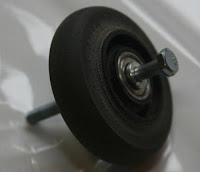
As you can see, the roller blade wheels are attached to the frame with carriage bolts.
The Rotating Parts
You can also see the wooden blocks and cabinet latches that lock the monitor in the horizontal position.
The bicycle rim and plywood rotate on the roller blade wheels. The plywood disk is made of two concentric 3/4" plywood circles glued together and is attached to the bicycle rim with a few screws through the spoke holes:
Because the roller blade wheels fits inside the channel in the rim, the top pair of roller blade wheels have to be installed after the rim and plywood.
Mounting the Monitor
I removed the monitor from it's plastic casing before I mounted it:
This probably wasn't necessary, but it is much cooler than having a beige plastic monitor case showing. I was happy to find that the CRT and electronics were enclosed in a metal case, especially after reading all the warnings about people getting the crap shocked out of them messing around inside a CRT. The monitor fits inside the large rectangle cut in the plywood disk and it is held in place with a couple of angle irons and screws. Here is a front view of the top right corner of the monitor in the cabinet that pretty much shows everything:
The white piece on top is a counterweight so that the monitor is balanced in the circle in both directions. It is a piece of leftover baluster from my deck railing filled with pennies and capped with wooden blocks on the ends so the pennies don't move or spill out when the monitor rotates.
Here is a rear view of the monitor mounted in the frame:
I originally was thinking of devising some way of rotating the monitor from the outside of the cabinet, but it is easy enough to just reach around and spin it with my hand that I think I am going to leave it as is.
Monitor Controls
One problem with a rotating CRT monitor is that if you rotate it when it is on, the colors get messed up because the magnetic field of the earth bends the cathode ray. Really. Fortunately, monitors have a degauss button for just this purpose. Since my monitor has a dedicated degauss button, along with a dozen other buttons for various other adjustments, all I had to do was move them someplace where I could reach them once the bezel was installed.
Sounds easy in concept. Then I did this:
Doh! I cut all the wires without labeling them so I had no idea which goes to which. I'm not usually that stupid. My excuse is that I am color blind and thought they were color coded. I didn't find out until I called Lori downstairs to help me match them and she broke the news.
I eventually sorted it out by deduction and soldered on a pair of DB25 connectors. I ordered a 6' serial extension cable and mounted the monitor control circuit board inside the front of the cabinet where I could easily reach it.
The Bezel
In order to make it presentable, I needed a bezel - something to hide the monitor case and rotating stuff. I started with the front of the original plastic monitor case. I cut a slot in the side for the cable to the remote monitor controls. I spray painted the visible parts of the plastic black.
Here are views of the monitor, in both the horizontal and vertical position:
The big white counterweight is necessary to keep the monitor from trying to spin back from the vertical position.
So that the bezel would completely cover everything except the monitor screen, I made it in two layers. The inner layer is a circle attached to the plastic monitor frame and rotates with monitor; the outer layer is attached to the cabinet and does not rotate. Both layers are made out of 1/4" hardboard and painted black. I'm going to add bezel art soon.
Here are pictures of the front and back of the inner bezel.
The inside edge of the bezel is beveled to match the angle on the plastic monitor case.
The pieces of MDF fit on either side of the plastic monitor case. Note the screws that protrude slightly through the MDF - they fit into holes drilled into the side of the plastic monitor case and hold it surprisingly firmly.
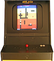
This is what the cabinet looks like with the inner bezel installed:
The outer bezel is a piece of 1/4" hardboard painted black with a rounded square, slightly wider and taller than the width of the monitor screen. It is sorely in need of some cool arcade artwork:
The outer bezel fits into the monitor opening in the cabinet. The inside edges of the monitor opening are notched to hold the outer bezel:
There is another notch to hold a piece of 1/8" plexiglass on top of the outer bezel.
OK. Time for less blogging and more playing.


